Package jmri.jmrit.display.layoutEditor
Example
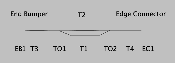
A small example layout:
Connectivity
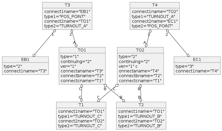
This is coded and stored as the following: (Some graphical attributes removed, reordered)
    <layoutturnout ident="TO1" type="RH_TURNOUT" continuing="2" ver="1" connectaname="T3" connectbname="T2" connectcname="T1" class="jmri.jmrit.display.layoutEditor.configurexml.LayoutTurnoutXml" />
    <layoutturnout ident="TO2" type="LH_TURNOUT" continuing="2" ver="1" connectaname="T4" connectbname="T2" connectcname="T1" class="jmri.jmrit.display.layoutEditor.configurexml.LayoutTurnoutXml" />
    <tracksegment ident="T1" connect1name="TO1" type1="TURNOUT_C" connect2name="TO2" type2="TURNOUT_C" class="jmri.jmrit.display.layoutEditor.configurexml.TrackSegmentXml" />
    <tracksegment ident="T2" connect1name="TO1" type1="TURNOUT_B" connect2name="TO2" type2="TURNOUT_B" class="jmri.jmrit.display.layoutEditor.configurexml.TrackSegmentXml" />
    <tracksegment ident="T3" connect1name="EB1" type1="POS_POINT" connect2name="TO1" type2="TURNOUT_A" class="jmri.jmrit.display.layoutEditor.configurexml.TrackSegmentXml" />
    <tracksegment ident="T4" connect1name="TO2" type1="TURNOUT_A" connect2name="EC1" type2="POS_POINT" class="jmri.jmrit.display.layoutEditor.configurexml.TrackSegmentXml" />
    <positionablepoint ident="EB1" type="END_BUMPER" connect1name="T3" class="jmri.jmrit.display.layoutEditor.configurexml.PositionablePointXml" />
    <positionablepoint ident="EC1" type="EDGE_CONNECTOR" connect1name="T4" linkedpanel="" linkpointid="" class="jmri.jmrit.display.layoutEditor.configurexml.PositionablePointXml" />
For TrackSegment objects, a connection is represented by the name of the other end, and the type (in type2 or type2) of the connection at the other end.
For example, a connection in object T1 to a turnout might give the turnouts TO1 name, and that the connection is to the TURNOUT_C leg of that turnout.
Connections to END BUMPERs and EDGE CONNECTORs don't quite fit that. The far end sees the connection to the EB and EC as to a POS_POINT, not
specifically a END BUMPER or EDGE CONNECTOR. There's no type1 value representing the far end of the connection from the EB and EC either.
But the EB and EC PositionablePoint knows what itself is through
its type variable, and that can be queried by following the link as there's only one connection to a PositionablePoint.
Turnouts also have a type variable to represent their geometry, i.e. RH, LH, Wye, etc.
Internals
Class Hierarchy
- The track is represented by a hierarchy of classes that's rooted in
LayoutTrackand completely disconnected from the PanelEditor classes. New classes are being added to represent the specific types previously implemented via type variables and conditional code.
LayoutBlockandLayoutBlockManagerare aNamedBeanpair. TheLayoutBlockis a group of track segments and turnouts that corresponds to a 'block'. It may contain aMemoryand/orSensor. If present, the sensor defines occupancy for the LayoutBlock. Each LayoutBlock is paired 1-to-1 with aBlockwhich it created; the Block has a specific form for its system name and the LayoutBlock's name as its user-name.BlockContentsIcon,MemoryIconinherit from the equivalents in thejmri.jmrit.displaypackage.LayoutEditorextendsPanelEditor- Multiple classes, including
LayoutEditorAction,LayoutEditorComponent,LayoutEditorToolBarPanel,MultiIconEditor, andMultiSensorIconFrame, extend Swing or AWT components. (AlthoughLayoutEditorComponentsounds like a base class for others, it's not; it's part of theLayoutEditorimplementation.) - Three subpackages provide specific services:
Class Relationships
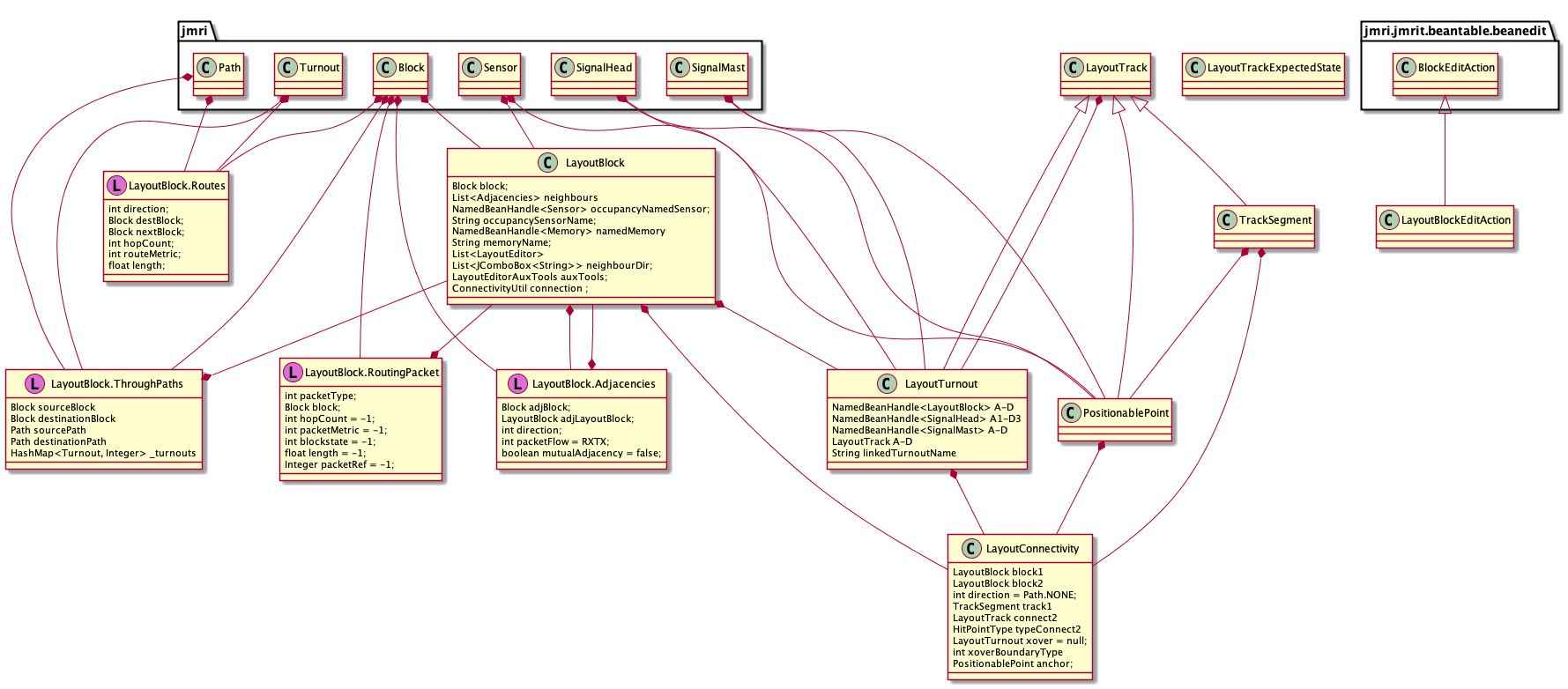
The LayoutBlock class is at the heart of the navigation web for layout-representing objects.
GUI
The Layout Editor window consists of a menu bar and an upper tool-bar that are all made with (basically) standard Swing components. Below that is a JPane containing the layout drawing itself.
The LayoutTrackView tree defines draw1 and draw2 methods that
draw two different representations of the track elements. These are only
invoked from {}@link jmri.jmrit.display.layoutEditor.LayoutEditorComponent}. LayoutEditorComponent is
a JComponent with a LayoutEditorComponent.paint(java.awt.Graphics) public method
that invokes a series of internal private methods to display the layers of the layout drawing.
That in turn is invoked via the usual repaint() mechanism, although it's often kicked
off by a call to LayoutEditor.redrawPanel().
Each of those layer private methods sets up graphics and method options, then
calls LayoutEditorComponent.draw1(java.awt.Graphics2D, boolean, boolean, boolean)
or LayoutEditorComponent.draw2(java.awt.Graphics2D, boolean, float). Those in turn
loop through a list from LayoutEditor.getLayoutTracks()
calling their individual LayoutTrackView.draw1(java.awt.Graphics2D, boolean, boolean) and LayoutTrackView.draw1(java.awt.Graphics2D, boolean, boolean)
methods.

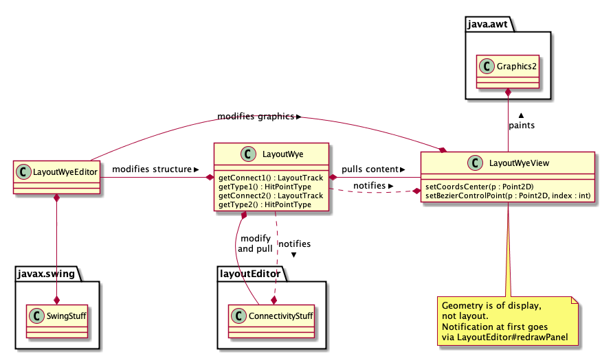
The goal is a MVC-like structure, with modifications to account for the mix of
swing components and AWT-style paint operations.
Persistance
The classes that have ConfigureXML partner classes are:BlockContentsIconLayoutBlockManager(registered with ConfigurationManager)LayoutEditor(registered with ConfigurationManager)LayoutShapeLayoutSlipLayoutTrackDrawingOptionsLayoutTurnoutLayoutTurntableLevelXingMemoryIconPositionablePointTrackSegment
ConfigureManager.
LayoutBlockManager is stored and loaded in the usual manager way, including the LayoutBlock objects. They are stored with the configuration information because they can be used on multiple LayoutPanels.
LayoutEditorXml handles the storing and loading of all the track and icon objects. It is stored at the user level ("Store Panels...")
A BlockValueFile stores and loads the value (internal temporary contents) of Block
objects from the BlockManager. It doesn't reference LayoutBlock objects.
More Info
User-level documentation is available here.(If these Javadoc were created with UML, the full-scale package diagram is also available.)
- See Also:
jmri.jmrit.entryexit,Section
-
Interface Summary Interface Description LayoutModels This interface serves as a manager for the overall layout model via collections of i.e. -
Class Summary Class Description BlockContentsIcon An icon to display a status of a Block Object.BlockValueFile Handle saving/restoring block value information to XML files.Bundle ConnectivityUtil ConnectivityUtil provides methods supporting use of layout connectivity available in Layout Editor panels.GlobalVariableIcon An icon to display a status of a GlobalVariable.LayoutBlock A LayoutBlock is a group of track segments and turnouts on a LayoutEditor panel corresponding to a 'block'.LayoutBlockConnectivityTools These are a series of layout block connectivity tools that can be used when the advanced layout block routing has been enabled.LayoutBlockConnectivityTools.BlocksTested LayoutBlockConnectivityTools.FacingProtecting LayoutBlockManager Implementation of a Manager to handle LayoutBlocks.LayoutConnectivity A LayoutConnectivity object represents a junction between two LayoutBlocks on a LayoutEditor panel.LayoutDoubleSlip A LayoutSlip is a crossing of two straight tracks designed in such a way as to allow trains to change from one straight track to the other, as well as going straight across.LayoutDoubleSlipView MVC View component for the LayoutDoubleSlipclass.LayoutDoubleXOver A LayoutTurnout corresponds to a turnout on the layout.LayoutDoubleXOverView MVC View component for the LayoutDoubleXOver class.LayoutEditor Provides a scrollable Layout Panel and editor toolbars (that can be hidden)LayoutEditorAction Start a LayoutEditor.LayoutEditorActionFactory LayoutEditorAuxTools LayoutEditorAuxTools provides tools making use of layout connectivity available in Layout Editor panels.LayoutEditorChecks A collection of tools to check various things on the layout editor panel.LayoutEditorComponent LayoutEditorFindItems A collection of tools to find various objects within the layout model(s) (temporary) Consider renaming to LayoutModelFindItems, or even merge to LayoutModelsLayoutEditorFloatingToolBarPanel This is the floating toolbar panelLayoutEditorHorizontalToolBarPanel This is the horizontal toolbar panelLayoutEditorToolBarPanel This is the base class for the horizontal, vertical and floating toolbar panelsLayoutEditorTools Layout Editor Tools provides tools making use of layout connectivity available in Layout Editor panels.LayoutEditorTools.BeanDetails<B extends NamedBean> LayoutEditorVerticalToolBarPanel This is the vertical toolbar panelLayoutEditorViewContext LayoutEditorViewContext is a memo object containing the graphical View context information for aLayoutEditorMVC instance.LayoutLHTurnout A LayoutTurnout corresponds to a turnout on the layout.LayoutLHTurnoutView MVC View component for the LayoutLHTurnout class.LayoutLHXOver A LayoutTurnout corresponds to a turnout on the layout.LayoutLHXOverView MVC View component for the LayoutLHXOver class.LayoutRHTurnout A LayoutTurnout corresponds to a turnout on the layout.LayoutRHTurnoutView MVC View component for the LayoutRHTurnout class.LayoutRHXOver A LayoutTurnout corresponds to a turnout on the layout.LayoutRHXOverView MVC View component for the LayoutRHXOver class.LayoutShape A LayoutShape is a set of LayoutShapePoint used to draw a shape.LayoutShape.LayoutShapePoint These are the points that make up the outline of the shape.LayoutSingleSlip A LayoutSlip is a crossing of two straight tracks designed in such a way as to allow trains to change from one straight track to the other, as well as going straight across.LayoutSingleSlipView MVC View component for the LayoutSingleSlip class.LayoutSlip A LayoutSlip is a crossing of two straight tracks designed in such a way as to allow trains to change from one straight track to the other, as well as going straight across.LayoutSlip.TurnoutState LayoutSlipView MVC View component for the LayoutSlip class.LayoutSlipView.TurnoutState LayoutTrack Abstract base class for all layout track objects (PositionablePoint, TrackSegment, LayoutTurnout, LayoutSlip, LevelXing and LayoutTurntable)LayoutTrackDrawingOptions Hold various values defining how to draw various LayoutTrack elements.LayoutTrackExpectedState<T extends LayoutTrack> Retain a LayoutTrack and its expected state.LayoutTrackView MVC View component abstract base for the LayoutTrack hierarchy.LayoutTurnout LayoutTurnout is the abstract base for classes representing various types of turnout on the layout.LayoutTurnoutView MVC View component for the LayoutTurnout class.LayoutTurntable A LayoutTurntable is a representation used by LayoutEditor to display a turntable.LayoutTurntableView MVC View component for the LayoutTurntable class.LayoutTurntableView.RayTrackVisuals LayoutWye A specialization ofLayoutTurnoutcorresponding to a wye turnout on the layout.LayoutWyeView MVC View component for the LayoutWye class.LayoutXOver A LayoutXOver corresponds to a crossover (connection between parallel tracks) on the layout.LayoutXOverView MVC View component for the LayoutXOver class.LevelXing A LevelXing is two track segment on a layout that cross at an angle.LevelXingView MVC View component for the LevelXing classMemoryIcon An icon to display a status of a Memory.MultiIconEditor Provides a simple editor for selecting N NamedIcons, perhaps for use in creating a panel icon.MultiSensorIconFrame Provides a simple editor for creating a MultiSensorIcon objectPositionablePoint PositionablePoint is a Point defining a node in the Track that can be dragged around the inside of the enclosing LayoutEditor panel using a right-drag (drag with meta key).PositionablePointView MVC View component for the PositionablePoint class.TrackNode TrackNode is a memo object specifying and returning track node informationTrackSegment TrackSegment is a segment of track on a layout linking two nodes of the layout.TrackSegmentView MVC View component for the TrackSegment class.TransitCreationTool The transit creation tool, is designed to be used by higher level tools to create transits between Beans. -
Enum Summary Enum Description HitPointType Enum denoting the different behaviors of different types of "HitPoints".LayoutBlockConnectivityTools.Metric LayoutBlockConnectivityTools.Routing LayoutEditorToolBarPanel.LocationFormat LayoutShape.LayoutShapePointType enum LayoutShapePointType Straight, CurveLayoutShape.LayoutShapeType enum LayoutShapeTypeLayoutTurnout.Geometry LayoutTurnout.LinkType LayoutTurnout.TurnoutType LevelXing.Geometry PositionablePoint.PointType
